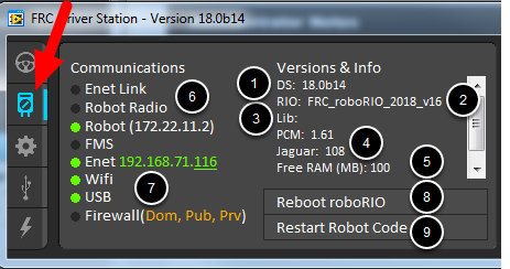

SmartDashboard and Shuffleboard launch the respective dashboards included with the C++ and Java WPILib installation. LabVIEW attempts to launch a dashboard at the default location for a custom built LabVIEW dashboard, but will fall back to the default if no dashboard is found. Default launches the file pointed to by the “FRC DS Data Storage.ini” file, by default this is Dashboard.exe in the Program Files\FRC Dashboard folder. Shift clicking on the dropdown arrow will show all roboRIO names detected on the network for troubleshooting purposes.ĭashboard Type - Controls what Dashboard is launched by the Driver Station. This controls the mDNS name that the DS expects the robot to be at. Team Number - Should contain your FRC Team Number. The Setup Tab contains a number of buttons teams can use to control the operation of the Driver Station: When the roboRIO brownout is triggered this will display “Voltage Brownout”. Status String - The Status String provides an overall status message indicating the state of the robot, some examples are “No Robot Communication”, “No Robot Code”, “Emergency Stopped”, and “Teleoperated Enabled”.
#Frc driver station axis m1013 code
The “Robot Code” indicator shows whether the team Robot Code is currently running (determined by whether or not the Driver Station Task in the robot code is updating the battery voltage), The “Joysticks” indicator shows if at least one joystick is plugged in and recognized by the DS.

The “Communications” indicates whether the DS is currently communicating with the FRC Network Communications Task on the roboRIO (it is split in half for the TCP and UDP communication). Major Status Indicators - These three indicators display major status items for the DS. See roboRIO Brownout and Understanding Current Draw for more information. The background of the numeric indicator will turn red when the roboRIO brownout is triggered. To change the team number see the Setup Tab.īattery Voltage - If the DS is connected and communicating with the roboRIO this displays current battery voltage as a number and with a small chart of voltage over time in the battery icon. Team # - The Team number the DS is currently configured for. It displays a selection of critical information about the state of the DS and robot:
#Frc driver station axis m1013 software
More information about the FRC Default Dashboard software can be found here.The Status Pane of the Driver Station is located in the center of the display and is always visible regardless of the tab selected. Installation instructions can be found here. The FRC Default Dashboard is included in the FRC Game Tools. It includes a tabbed display that can switch between viewing an image from a camera on the robot or a display of NetworkTables variables, a display of information regarding the joysticks and drive motors, an indicator of the robot IP and battery voltage, and a second tabbed display that can switch between examples of custom indicators and controls, a test tab for use with the Driver Station Test Mode and a Checklist tab that teams can use to enter a custom checklist to complete before each match. The FRC Default Dashboard serves as a an example of the types of feedback teams may want from their robot. The purpose of the Dashboard is to provide feedback about the operation of the robot. The FRC LabVIEW Dashboard is the default dashboard program installed with, and automatically launched by, the FRC Driver Station.


 0 kommentar(er)
